This post describes how the parametric feature history of one of our parts, the NVGRA-31, was moved from Autodesk Fusion 360 to SolidCraft, an open-source parametric CAD application. It covers the extraction method, how the rebuilt model was verified, the kernel defects found along the way, and the current limits.
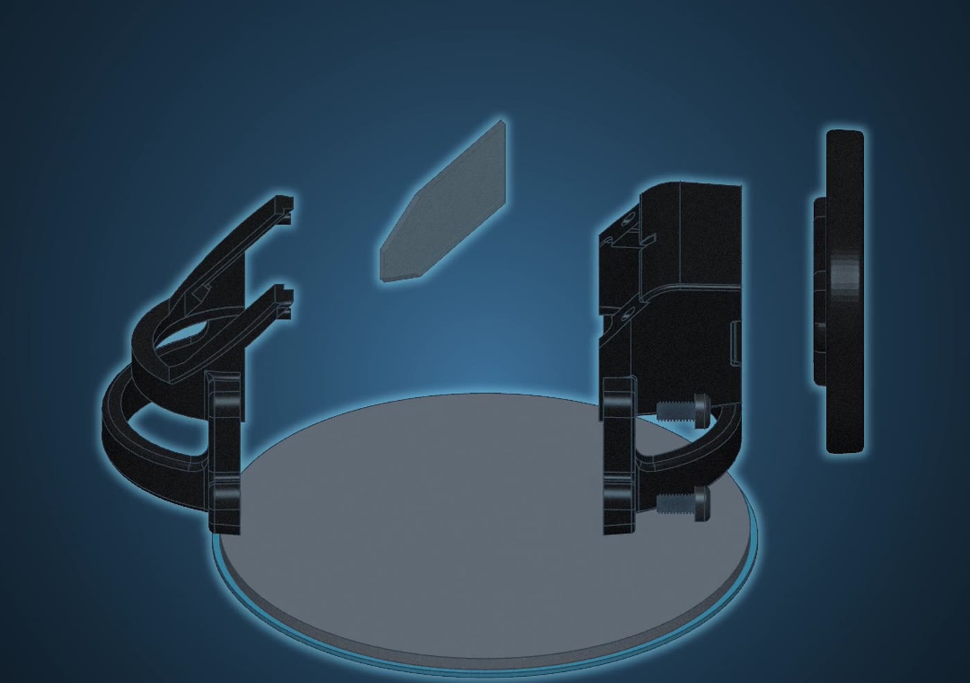
Background
SolidCraft was first published in October 2026. The work described here started about 11 days after that release and ran for roughly four weeks, during which the application changed daily.
The motivation was practical: to stop depending on a subscription CAD tool, and to hold our designs in a form we can read and rebuild ourselves.
The test part has 53 timeline steps in Fusion:
| Step type | Count |
|---|---|
| Extrude | 29 |
| Draft | 10 |
| Sketch | 6 |
| Fillet | 3 |
| Construction plane | 2 |
| Chamfer | 1 |
| Component occurrence | 2 |
| Total | 53 |
Why STEP export is not enough
Fusion exports geometry as STEP. A STEP file describes the final solid only. It contains no sketches, parameters or features, so the part cannot be edited at an earlier step and rebuilt.
The editable definition of the part is its timeline: the ordered list of sketches and features.
Fusion’s own archive format, .f3d, does carry the timeline. It is a proprietary format with no published specification, and we know of no other CAD tool that rebuilds the feature history from it.
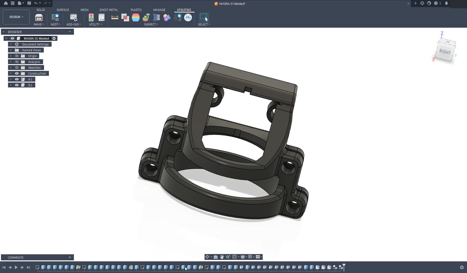
Moving the timeline marker back returns the model to its state at that step:
Extracting the timeline through the Fusion API
Fusion provides a public Python scripting API that can read a design’s parameters, sketches and features. The extraction uses only that API, run inside Fusion under the account that owns the designs. The .f3d file format is not read or reverse-engineered.
We wrote two scripts that recover the timeline of your models. Both run inside Fusion, and both are published (see Availability):
ExportAllDesignswrites each design as STEP and records the volume and surface area that Fusion reports for it. Those values are the reference for later checks.ExtractTimelinewrites the feature history as JSON: user parameters with their expressions, sketch geometry and constraints, and each feature with its inputs.
An LLM coding agent (Claude Code) operated the Fusion user interface to run the scripts. It used a small driver that sends mouse clicks to the Fusion window and reads the screen: it opened Utilities → Add-Ins → Scripts and Add-Ins, selected the script and started it. After each click the driver confirmed that Fusion was still the foreground window.
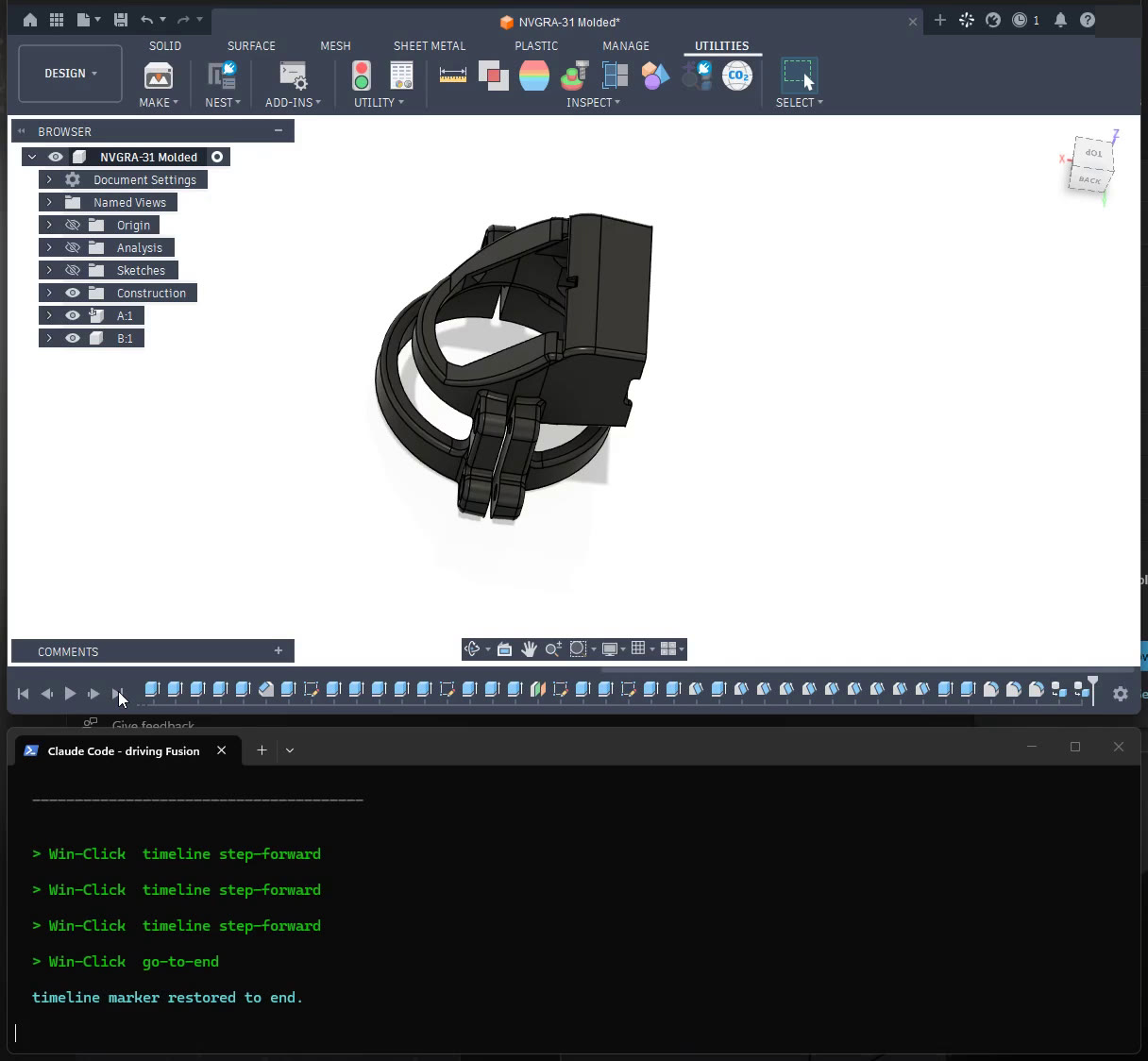
Two parts of the extraction method are worth describing.
Geometry-based references instead of topology IDs
A feature such as a fillet refers to specific edges. Fusion identifies them by internal IDs, which have no meaning in another CAD system. The extractor therefore records geometry instead: a point lying on each referenced edge or face, a point inside each sketch profile, and each sketch’s coordinate frame.
Example: for a fillet on the rim of a boss, the recipe stores a point on that rim. On replay, SolidCraft selects the edge that passes through the point. SolidCraft already accepts selections in this form.
Rolling the timeline back to read a fillet’s input edges
A fillet replaces the edge it rounds, so that edge does not exist in the finished body. Reading fillet inputs from the final model failed for 264 of the 271 fillet and chamfer steps in the first survey.
The extractor now sets the timeline marker to the step in question, reads the edges as they existed at that point, and restores the marker. The design is not saved. With this change all 271 steps were recovered.
Mid-October compared with 7 November
The first run, in mid-October, covered every design in one Fusion account. Few designs survived the whole trip. The later column is the latest recorded run of the timeline replay, on 7 November, for one part: the 53-step NVGRA-31, which has had the most work. The account-wide run has not been repeated, so the two columns are not like for like.
| Mid-October 2026 | 7 November 2026 (latest recorded run of the timeline replay) | |
|---|---|---|
| Scope | 270 designs, 2,797 timeline steps | One part, 53 timeline steps |
| Fillet and chamfer inputs read from Fusion | 7 of 271 steps before the rollback method; 271 of 271 after it | All read |
| Designs translated in full | 50 | The test part: yes |
| Rebuilt without error | 21 of those 50 | All 40 feature steps before the fillets reproduce Fusion’s volume at that step |
| Fillets | Refused on most curved edges | The part’s three fillet features build some of their edge sets, not all |
| Our pull requests merged upstream | None yet | Seven, five of them fillet, draft and blend kernel fixes |
Completing the steps that did not replay
The table raises an obvious question: if three fillet features did not replay in full, how was the part finished?
By that point the agent session holds the whole recipe and a verified body for every earlier step. It knows which edges each remaining feature was meant to round and what the result should look like, so the remaining steps can be completed by other means. Five were used:
- Fix the kernel. A refusal that was a real kernel defect was reduced to a minimal case, fixed and sent upstream, as described under Kernel defects and upstream fixes. Each fix let more edge sets build on the next run.
- Build the same shape another way. Where a feature would not replay as recorded, the intended shape was produced differently: one fillet split into separate calls per edge set, features reordered, or a round replaced by geometry drawn in the sketch. Each substitute is recorded as a deviation from the timeline.
- Change a fillet’s order or radius. Named parameters were kept as designed. A fillet’s radius or position in the order was allowed to change where that made it build, and each change is recorded as the designed value and the value used.
- Leave out rounds the mold produces anyway. The mold is milled, and the cutter’s radius rounds the part’s small outside edges without their being modeled. Small rounds of that kind were omitted. Broad curves, and small rounds on inside edges, were kept.
- List what remains. Any round still omitted or built smaller is written to a list that travels with the part, so nothing is missing silently. Those can be added in a later revision or in the original CAD system.
Every substitute was checked the same way as a replayed step: the body passes the kernel’s full validity check, a fine tessellation and a STEP round trip, and rounded edges are confirmed with the sphere test described under Step-wise reconstruction and verification.
The result is a valid, editable body that was fit to submit for a molding review. It is not a feature-for-feature copy of the Fusion model, and the list of remaining differences is part of the deliverable.
Step-wise reconstruction and verification
The first reconstruction attempts replayed the whole recipe in one run and compared only the final body with Fusion’s. When they differed, the cause could not be located.
The method that worked replays one step at a time:
- Build step n in SolidCraft.
- Compare the result with Fusion’s model at step n: body volume and face count.
- If they agree, accept the step and continue with n + 1.
- If they do not, stop. The difference is attributed to step n and investigated before any later step is built.
A second, independent check is used for rounds, because a fillet command can report success without having rounded the requested edge. A small sphere is placed at the position of the original sharp corner and intersected with the body: on a sharp edge the sphere overlaps the solid, and on a rounded edge it does not. Before use, this check was validated on edges known to be sharp and edges known to be rounded.
A step is recorded as complete only when these checks pass.
Kernel defects and upstream fixes
Some steps failed because SolidCraft’s geometry kernel refused an operation that is valid. Examples: a round that ends against a step lower than its radius, a round that continues across a smooth edge onto the next face, and a round at the base of a boss whose axis is half a degree off perpendicular.
Each failure was first checked to rule out an error in our own tooling, which accounted for several. Confirmed kernel defects were handled as follows:
- Reduce the failure to a minimal case on invented geometry (a block, a boss, a step) with no relation to the real part.
- Add a regression test on that case that fails.
- Change the kernel until the test passes, with the existing test suite unchanged.
- Rebuild the real part. A fix is submitted upstream only if it measurably improves the real part.
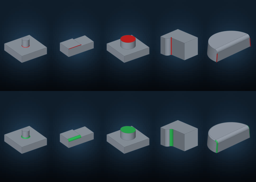
Seven of our pull requests have been merged into SolidCraft so far, most of them kernel fixes found this way, and others are in review. One regression we reported was reproduced independently by a community member, who built the commits on either side of the change.
Several agent sessions ran in parallel, one coordinating, each working on a separate defect or part of the rebuild. Builds ran on several machines.
Applying a manufacturability review
A rebuilt timeline can be edited, which a STEP import cannot. The part was sent to Proto Labs for an injection-molding design review. The review returned a short list of required changes, including:
- reverse the draft direction on the insert pockets and screw holes, so that they release from the mold;
- remove rounds that cross the parting line.
These changes were made in the rebuilt SolidCraft timeline the same day. Each one was rendered from the same viewpoint as the corresponding callout in the review, for comparison:
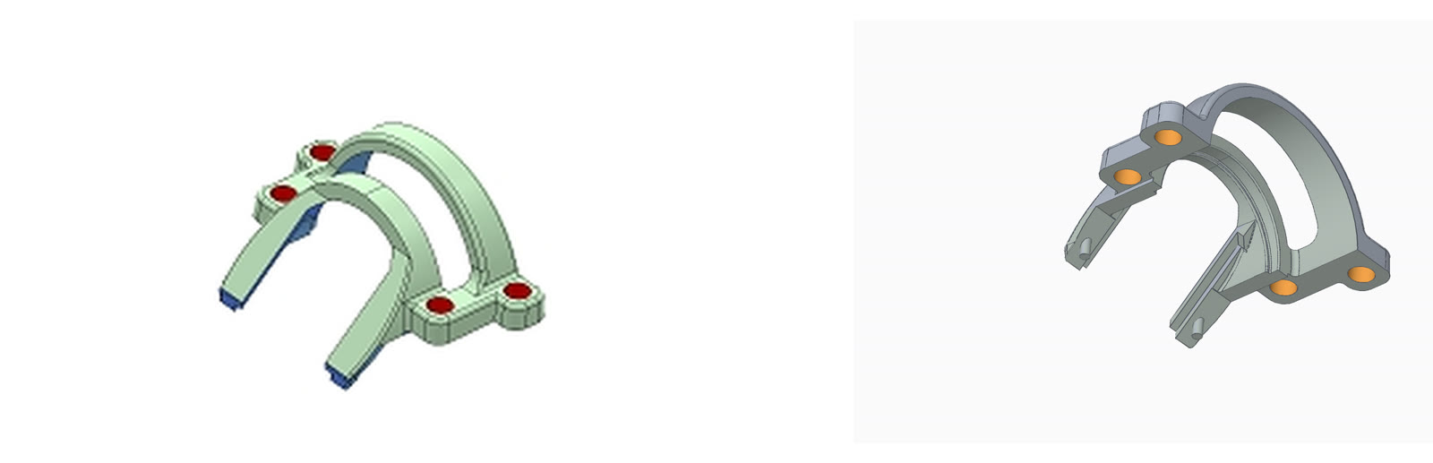
Left: the review’s callout on the insert pockets. Right: our model after the change, with changed faces in orange.
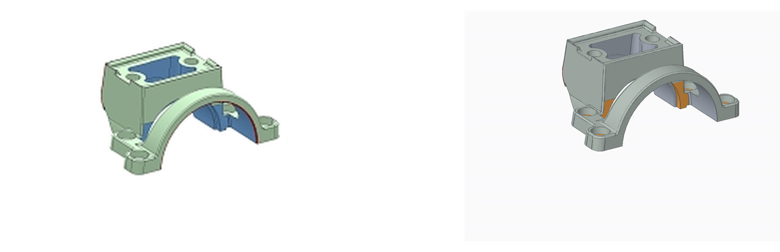
Left: a round crossing the parting line. Right: the round removed. Colors are analysis colors, not the part’s.
The revised part is being prepared for resubmission.
Results and limitations
The extraction and translation were first run across one Fusion account in mid-October 2026. The figures below are from that run and have not been repeated since; SolidCraft’s kernel has changed substantially in the meantime.
| Measure (mid-October 2026) | Value |
|---|---|
| Designs surveyed | 270 |
| Timeline steps | 2,797 |
| Designs with no modeling history (imports, assemblies) | 106 |
| Modeling steps translated | 91% |
| Designs translated in full | 50 |
| Of those, building without error | 21 |
For designs with no modeling history, STEP remains the appropriate route.
Feature types that translate: sketches (with constraints and dimensions), extrude, revolve, fillet, chamfer, shell, draft and offset faces. Not yet translated: loft, sweep, hole, pattern, mirror, combine, thread, sheet metal and assemblies.
Most build failures in the survey occurred in the kernel, not in translation.
The method requires a licensed Fusion installation and access to the original designs, because extraction runs inside Fusion.
Availability
- SolidCraft: solidcraft.io and github.com/tangency-labs/solidcraft
- The extraction and translation scripts: github.com/acbrazzl/fusion-to-solidcraft (Apache-2.0)